Prerequisites
Before you start, you will need to secure the following items which are not included in the kit.
- One (1) Wireless IFB Receiver (AKA Comtek)
- Three (3) Walkie Talkies
Basic System
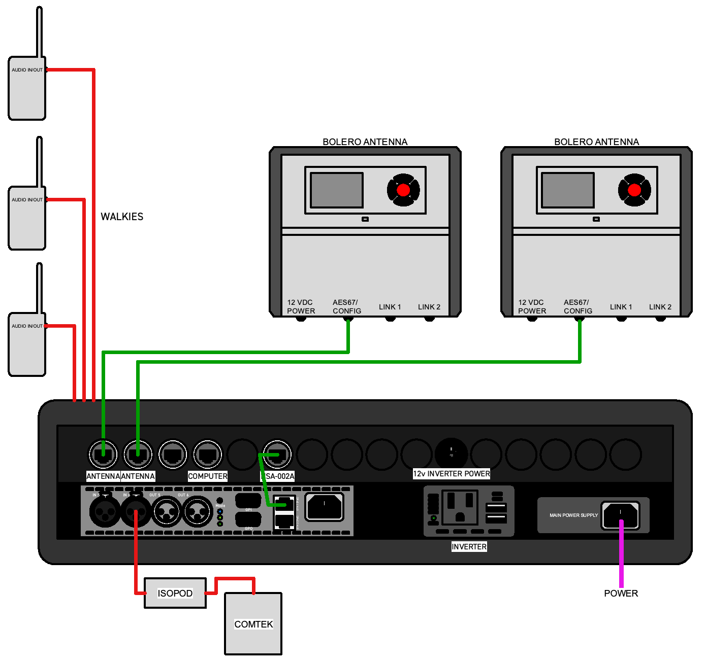
- Take the back cover off the 2U rack case (Case 2) and put it somewhere where it can be found at the end of the job. The AC power cable should be found stored in one of the covers.
- Find the IEC C14
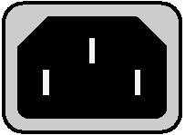 power connector on the yellow power supply mounted at the lower right of of the rack case, on the same side as the patch panel. Connect the AC power cable.
Attention
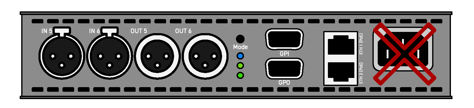
There is also an IEC C14 connector on the NSA-002A Network Stream Adapter.
DO NOT use this connector. It will not power the system correctly.Instead, connect to the yellow power supply all the way to the right side on the bottom shelf. This provides power to the network switch which supplies the whole system using Power over Ethernet (PoE).
- Connect the other end of the AC power cable to the uninterruptible power source. You should see lights blinking on the NSA-002A when power is connected.
- Get the two Bolero Antennas and RJ45 EtherCon cables from Case 1.
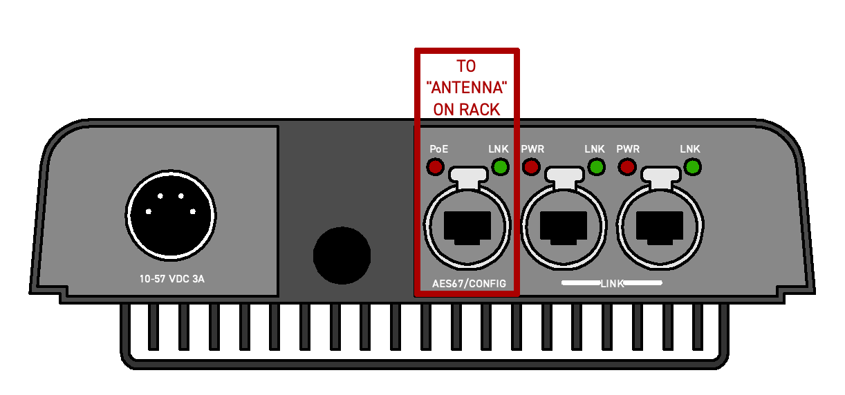
- Using RJ45 EtherCon cables, connect each Antenna’s
AES67/CONFIGport to one of theANTENNAports on the rack case patch panel. The Antennas should start to power up.
Unusual Circumstances
When working on small or inaccessible locations, keep in mind that the Antennas can be separated from the NSA-002A, and from each other, by up to 300m/900ft of CAT5 ethernet cable.
Attention
Only one of the Antennas has a “Standalone License.” This is indicated by the letters SA in the lower left of the Antenna’s display. This Antenna must always be a component of the system.
Walkie Interface
- Make three labels: CAMERA, ELECTRIC and GRIP.
- Attach a label to each of the three walkies.
- Set each walkie to the channel used by the department corresponding to its label.
- Turn each walkie on and set the volume to about 50%.
- Press the talk button and listen for the “low battery” chirp. If the battery is low, replace it.
- Coming through a hole in the patch panel you will find a loom of three walkie-talkie cables with Motorola M-type 2-pin male connectors. They are labeled
CAMERA,ELECTRIC, andGRIP. Connect each cable to the corresponding walkie talkie.
Monitor IFB (Comtek) Interface
- Determine whether the wireless IFB (Comtek) receiver’s headphone output is Tip-Ring-Sleeve (TRS) or Tip-Sleeve (TS).
Info
Comteks are typically Tip-Sleeve (TS).
Lectrosonics are typically Tip-Ring-Sleeve (TRS).
Ask the sound mixer or utility; they will know.
- In the pouch in Case 1 you will find two Whirlwind ISOPOD summing transformers. One has an ORANGE cap at the end with the headphone jack, the other has a BLACK cap. Refer to the table below to select the correct transformer and jumper cable.
- In the same pouch with the ISOPODs you will find some short 3.5mm jumper cables. Select one with connectors (TRS or TS) that correspond to the IFB receiver and the ISOPOD you selected. Connect the IFB to the ISOPOD.
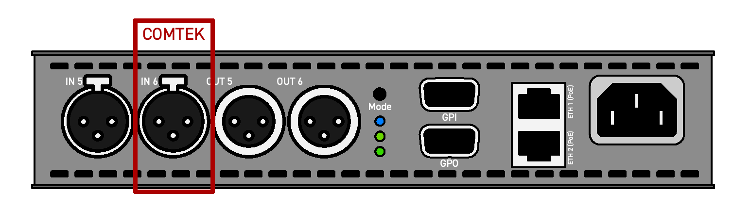
- Get a 3-pin XLR mic cable from the same pouch. Connect the XLR output from the ISOPOD to
IN 6on the NSA-002A using the XLR cable. - Turn the wireless IFB receiver on and set the volume to about 75%.
| Headphone Jack | Cable Connector | ISOPOD |
|---|---|---|
| Tip Ring Sleeve (TRS) | 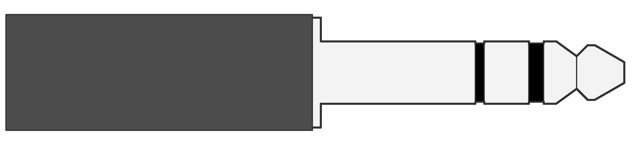 | 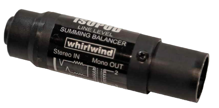 |
| Tip Sleeve (TS) | 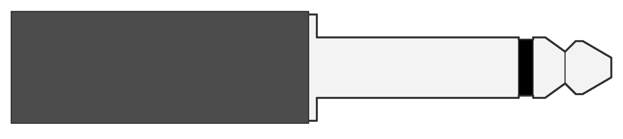 | 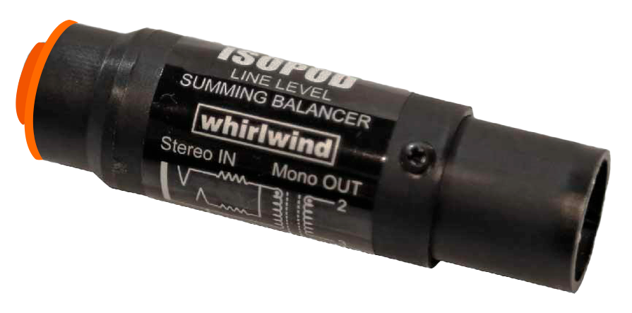 |
Power Considerations
A primary concern with the system is to keep it powered at all times, even during transitions–when carts are moving between stages or from one part of a location to another. There are a few ways to achieve this.
CyberPower CP1500 UPS
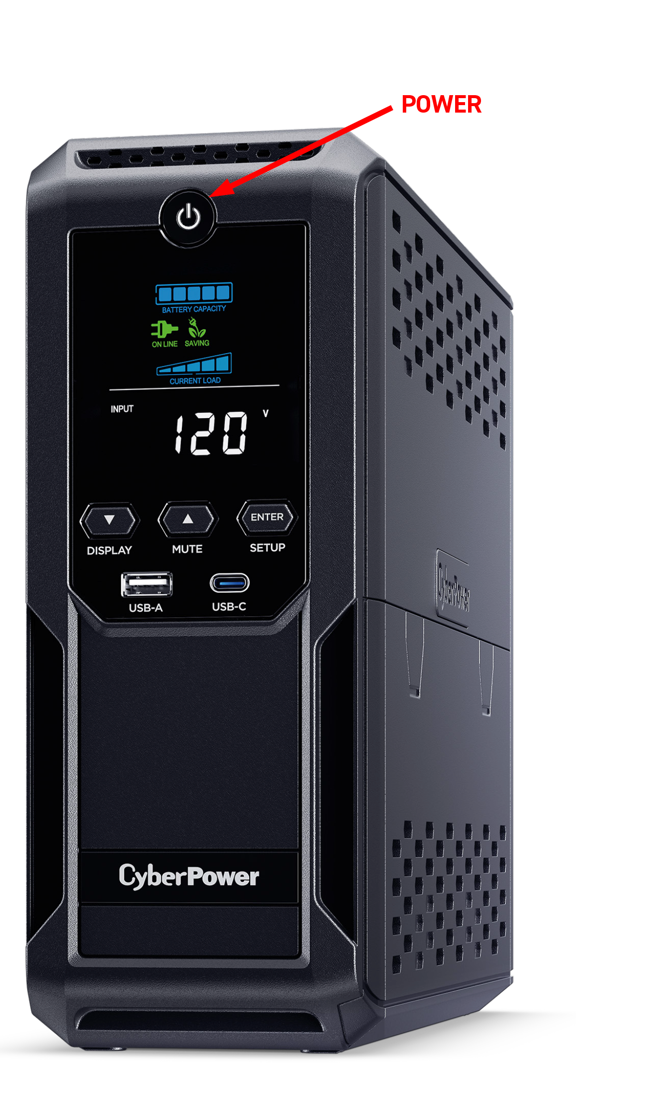
This is the primary way we power the system. It is located on the shelf at the back of the headset cart. Use the power button to turn it on at the start of the day, and turn it off at the end of the day.
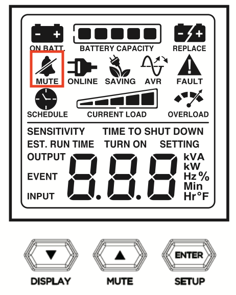
Double check that the MUTE icon is displayed on the screen. If it is not, press the MUTE button for 2 seconds, until the symbol appears.
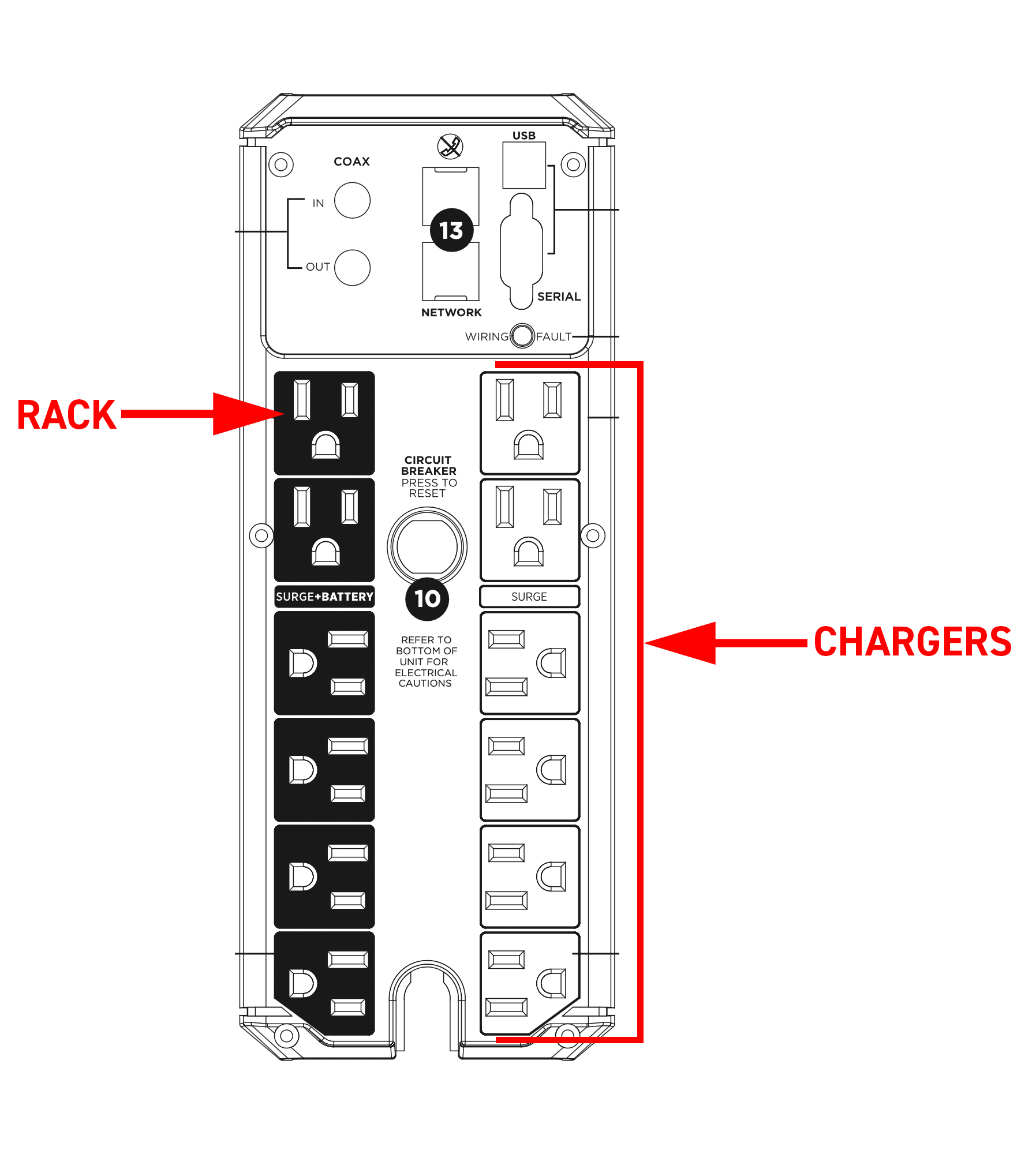
Plug the rack power cable into a SURGE+BATTERY outlet. All of the chargers and the wifi router should be powered from the SURGE outlets. These will not be powered when the unit is unplugged.
Eco-Flow River 2 Pro
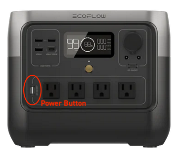
This usually runs the DP cart, but can also be used to power Boleros. This will run the system for 5 hours or so without having to charge. The strategy is to keep it plugged in once we have settled on stage or location, so that the battery always stays charged.
TWO THINGS TO DOUBLE CHECK
- Check that the IEC C13 cable that charges the power bank is fully connected in the back. It will sometimes come loose. Once you have connected to AC power, insure that the display shows the unit is charging.
- There is a button next to the 120v power outlets that switches the outlets off and on. Confirm that the button is glowing white after you connect or disconnect the power bank from external power. It will sometimes switch off during transitions.
Camera Batteries
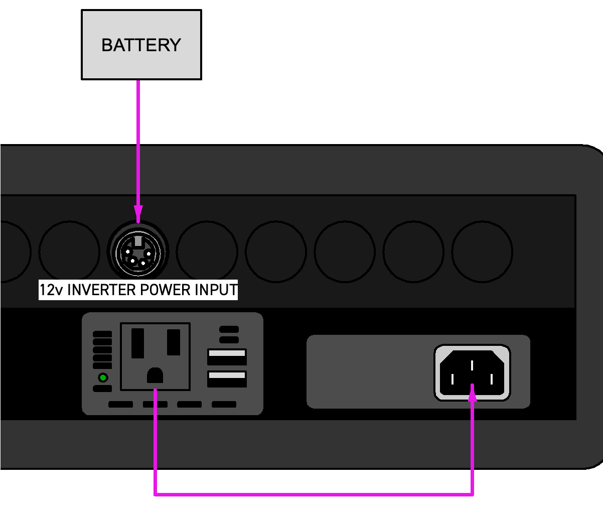
When the system needs to be somewhere AC power is not available, such as on an insert car or small location, the antennas and rack box can be powered by a camera battery. Next to the power supply on the bottom shelf of the rack case you will find a KondorBlue inverter. Above the inverter, in the patch panel, is a 4-pin XLR connector.
- Plug the male end of the AC power cable into the KondorBlue inverter. (The female end should remain connected to the yellow power supply on the bottom shelf of the rack.)
- Plug a battery into the 4-pin XLR connector on the patch panel using a standard camera battery cable. There is a Gold Mount plate with a 4-Pin XLR cable in Case 1 or the cart drawer, if you want to use Dionics.
Info
There is no need to connect battery power to the inverter unless you are using it to power the rack. It has a small fan that can sometimes get noisy. If we don’t need it, don’t give it power.